Benutzer-Werkzeuge
Inhaltsverzeichnis
Advanced Microcontroller
Definition
A microcontroller is a highly integrated chip which includes, on one chip, all or most of the parts needed for a controller. The microcontroller could be called a “one-chip solution”. You can see this parts on the following scheme.

As you can see in the picture a microcontroller consists of a central processing unit (CPU), random access memory (RAM), erasable programmable read only memory (EPROM), I/O and other Serial and parallel Interfaces.
Microcontroller vs. Microprocessor
A microprocessor
- is a normal CPU
- has no periphery devices (memory, i/o, etc.)
- communicates with external devices via a data bus
History overview
One of the first Microcontroller was invented by Gary Boone for Texas Instruments in 1971. It includes nearly everything to build a calculator except of display and keypad control. In that time, there was a race to build the first “calculator-on-a-chip”. The next famous microcontrollers have been invented by Intel, the Intel 4004, which was the first controller that has been produced in series. The Intel 8048 followed a few years later and was used in an IBM Keyboard. The Intel 8051 (invented in 1980) is probably the most known microcontroller and is often used nowadays in embedded systems like washing machines or USB flash drives. The first so called “advanced microcontroller” came up in 1989/1990. This kind of new microcontrollers have an electrically erasable and programmable ROM memory, which can be programmed, erased and reprogrammed with the help of just electrical signals. This was a door opener not just for modern microcontroller sets like the Lego Mindstorms, Arduino, Raspberry Pi and many more but also for mobile computing, Internet of Things and wearables.
Arduino
The Arduino is the worlds most famous and mostly used microcontroller. It was released in 2005 with open source hardware and software. So until today countless addons, user projects and a huge community developed. Compared to other advanced microcontrollers the Arduino has relatively slow hardware. In exchange it is the smallest, lightest and cheapest (only 25$) of them. So the main usage are not difficult operations like gaming or multimedia systems but rather small chips, for example used for wearables, machines or in general everywhere where only few (and easy) calculations are needed and a lightweight controller is advantageous. This is a picture of the recent Arduino USB board (Arduino Uno):

Technical details
- 16MHz clock speed
- 32KB flash memory
- 14 digital I/O pins
- 6 of them provide PVM output
There are also some other Arduino boards which are not USB based. For example (on the left) the Arduino BT (BlueTooth) or (on the right) a serial version:


More information on available Arduino boards, the community and tutorials can be found on https://www.arduino.cc/.
While early versions were distributed as self assembly kits where soldering the parts to the board was mandatory later versions come as pre-assembled kits which can be expanded by other „shield“ cards, increasing the amount of possible hardware attachments. These shields are for example used to increase the amount of I/O ports, adding a LCD display or to add very special ports for which no space on the basic board was left. Here are some exemplary pictures of different shields:


From left to right they show: a) a LCD Display b) controllers c) some shields stacked on one board
Arduino programs are really easy to code. The board already brings a text editor and an IDE with it which really help to simplify the coding. The language is C/C++ which can be difficult but the IDE hides all difficult things like headers from the user (unless he wants to work with them). In our sample project you can find a code example.
The following is a nice Arduino project we found on YouTube, a stroboscope built on an Arduino and a broken XBOB DVD drive:
Basically the Arduino turns the light on and off while the DVD drive turns the models which, in combination, creates the illusion of a dancing figure. More information on this project can befound on http://elabz.com.
Sample Project
The Arduino love-o-meter is a simple sample project which uses a temperature sensor. We extended this sample with a rgb-lcd screen which shows the actual temperature. The three leds indicates the temperature, from cold (blue) to high (red).
For this sample project you need the following parts:
- Arduino Uno
- Breakout board
- 3 leds
- three 220 ohm resistors
- Grove starter kit shield
- Grove starter kit temperatur sensor
- Grove starter kit rgb-lcd screen
Wirering
At first you have to connect all the parts. Therefore you have to put the leds and the resistors on the breakout board. Connect it to the arduino grove shield like in the picture. To control the leds we will use the digital output ports of the arduino. After that connect the tempurate sensor and the rgs-lcd screen to the grove shield.

Code
#include <Wire.h>
#include "rgb_lcd.h"

rgb_lcd lcd;

const int colorR = 0;
const int colorG = 255;
const int colorB = 0;

const int pinTemp = A0;      // pin of temperature sensor

float temperature;
int B=3975;                  // B value of the thermistor
float resistance;

void setup() {
    Serial.begin(9600);
    lcd.begin(16, 2);

    lcd.setRGB(colorR, colorG, colorB);

    // Print a message to the LCD.
    lcd.print("Temperature");

    // set the LED pins as outputs
  // the for() loop saves some extra coding
  for (int pinNumber = 2; pinNumber < 5; pinNumber++) {
    pinMode(pinNumber, OUTPUT);
    digitalWrite(pinNumber, LOW);
  }
}

void loop() {
  int val = analogRead(pinTemp);                               // get analog value
    resistance=(float)(1023-val)*10000/val;                      // get resistance
    temperature=1/(log(resistance/10000)/B+1/298.15)-273.15;     // calc temperature

    Serial.println(temperature);

    lcd.setCursor(0, 1);
    lcd.print(temperature);
    lcd.setCursor(6,1);
    lcd.print("C");

    if(temperature<26){
      digitalWrite(2,LOW);
      digitalWrite(3,LOW);
      digitalWrite(4,HIGH);
    }
    else if(temperature>=26 && temperature < 28){
      digitalWrite(2,LOW);
      digitalWrite(3,HIGH);
      digitalWrite(4,LOW);
    }
    else{
      digitalWrite(2,HIGH);
      digitalWrite(3,LOW);
      digitalWrite(4,LOW);
    }

    delay(500);          // delay 1s
}
Intel Edison

„We were in denial on tablets. It put us in a hole, and we are paying the price for that right now,“
Andy Bryant
When Andy Bryant told his investors this sentence, he already recognized, that intel missed the opportunity to claim the market of mobile computing as theirs. From that point on, one thing was clear: Intel will not miss the the next technological evolution. As the wearable market then started to grow, they developed a chip to compete in the growing market. Their goal was to create a chip small enough to built it in wearables, but also powerful enough to be able to run everything on this small chip. The outcome of this was the Intel Edison chip. But that was not enough. Intel oragnised a huge competition called „Make it Wearable“. With this Competition they wanted to motivate developers from all over the world to take their intel Edison chip as brain of their invention. With a grand prize of 500.000$ Dollars they achieved their goal and received thousands of project ideas from people all over the world.Technical Details
- Processor: Intel Atom Dual-Core CPU mit 500 MHz in addition a Intel Quark Microcontroller with 32-Bit and 100 MHz
- RAM: 1 GB DDR3
- Internal Memory: 4 GB
- WiFi: Broadcom 43340 802.11 a/b/g/n, Dual-Band (2.4 und 5 GHz)
- Bluetooth: 4.0
- Firmware: Yocto Linux v1.6
- Various GPIO Pins on the breakout board
- Size: 35.5 × 25.0 × 3.9 mm
- Cost: 63.99$
How it works
The Intel Edison is powered by an Intel Atom Processor. For the processing there is 1 Gigabyte of Ram. It also has an internal flash memory about 4 Gigabyte. To handle the communication between the Intel Edison and the outer world, there are 2 Modules on board. To have the possibility to access the Internet there is a WiFi Chip integrated. In addition to communicate with your surroundings the Intel Edison has a bluetooth Chip. The Intel Edison Chip can be extended with a breakout board to have multiple additional options. You then can access various GPIO- and other Pins.

Where to find Help
If you encounter any problems while developing for the Intel Edison it is easy to get some help. You then have the opportunity to contact the support of Intel, if you encounter hardware problems, or depending on the programming language you have chosen go to one of the big forums. You can reach the support of Intel 24/7, which makes it really easy to get some help directly from the publisher of the hardware. If you for example have chosen to program in Arduino, you can go into one of the big Arduino forums to get really fast help, or just look around if anyone already encountered that specific problem. There also grew up a large Forum specific for the Intel Edison. There are solved nearly all of the common problems you may encounter on your way of developing your project. You can reach this Forum by clicking on the Link below. https://communities.intel.com/community/tech/edison/content
If you want to find some sample projects, there is a nicely built up site called Instructables.com. There you can find lots of projects and get the instruction how to built it. The only problem is, if you want to get the instructions, you have to have a registered account and for many of them you have to pay a small amount of money. Nevertheless you get a detailed instruction on how to build it and you are able to contact the author of the project if you need help.
http://www.instructables.com/id/Intel-Edison-Projects/
Make it Wearable

1. Nixie
Team Nixie claimed the grand price to be theirs. With a hand wrist quadcopter they managed to defeat the other teams. Their quadcopter mainly focuses on times, when you want to have a selfie, but have no hand free to take it, or just want to have an amazing perspective. The quadcopter's brain consists of an intel edison chip to controle all of its moves and intelligent performances. If the user turns his arm, the engine of the quadcopter starts and it is ready to take off. If it then is thrown away, it will fligh a little bit, then turn, take a selfie and flighs back to the user.
2. Open Bionics
The second place went to the team Open Bionics. They developed a robot hand for handless people. As they wanted to make it as affordable as possible, they decided to make their hand be producable using a 3D printer. With this achieved, they are now probably able to sell it for under 1.000$ which is quiet cheap if its compared to a not 3D printed robot Hand. They cost around 18.000$. Additionaly they want to make it open source, so that everyone can improve and also design their hand on their individual style and needs.
3. ProGlove
On the third place there is the team ProGlove. They evolved an intelligent glove which helps workers to improve their workflow. They achieve this by adding a lot of sensors to the glove. That allows the glove to recognize if the worker is following the right order or if he misses out some steps. If the worker is missing something, the glove will show a big red cross to show the user that there is something wrong. If he then does the right thing, the red cross will turn into a green tick.
How to Programm
The Intel Edison offers a variate of programming languages, which makes it quiet comfortable. If you have already implemented software for Arduino, but the Arduino was way to slow to manage the programm, you can now simply launch this software on the Intel Edison. This is possible because the Edison supports the Arduino IDE. But the Edison not only supports Arduino, it also offers for C/C++, Phython, Node.JS, HTML5 and Java Script. This makes it easy to use for the developer, because if the HTML5 and Java Script support works properly, it can be easily used for web applications. And as web applications become more and more important this is a nice feature.
Building a lightning navigation Indicator
Overview
In this section, I will explain to you, how you can build your own Lightning stripe Navigation Tool or anthing else using a NeoPixel LED stripe. You don't have to have electrical engineering skills, or at least not that deep knowledge. If you have everything prepared it will only take you about half an hour.
What you need
- Intel Edison + Breakout Board
- Some wires
- A large capacitor (1000 µF, 6.3V or higher)
- A ~470 ohm resistor
- External Power Supply (5V, 10A), if you want to use more then 8 LED's
- NeoPixel LED Stripe, or something similar
- A Breadboard
- A Wire Stripper
- A Soldering Iron
Setting Things Up
 At first make sure that your Edison is working and connected to the breakout board. Open the head of your Power supply so that you can reach the plus and minus pole of it. If the end of your NeoPixel looks like the one on the picture, you than have to cut the white wire. This white wire is the data input, which we will later use to tell the NeoPixel what to do. You have to cut it, because we want to solder the wire to the NeoPixel.
If your NeoPixel has no wires, you have to solder a wire for each pin you see on the NeoPixel. Depending on the Model of your stripe the order will be Ground(GND) on top, then Data Input(DIN) in the middle and +5 Volt (+5V) at the end. Important is, that you take the one end of the NeoPixel where the DIN is located and not the Data out. When you take the wrong end, nothing will happen later on if you start the programm. This is because you want to tell the NeoPixel what to do (so send Data In) and not want to get data from the NeoPixel(Data OUT).
At first make sure that your Edison is working and connected to the breakout board. Open the head of your Power supply so that you can reach the plus and minus pole of it. If the end of your NeoPixel looks like the one on the picture, you than have to cut the white wire. This white wire is the data input, which we will later use to tell the NeoPixel what to do. You have to cut it, because we want to solder the wire to the NeoPixel.
If your NeoPixel has no wires, you have to solder a wire for each pin you see on the NeoPixel. Depending on the Model of your stripe the order will be Ground(GND) on top, then Data Input(DIN) in the middle and +5 Volt (+5V) at the end. Important is, that you take the one end of the NeoPixel where the DIN is located and not the Data out. When you take the wrong end, nothing will happen later on if you start the programm. This is because you want to tell the NeoPixel what to do (so send Data In) and not want to get data from the NeoPixel(Data OUT).
Wirering
So now we have to connect the Intel Edison to the NeoPixel stripe. We therefore use the breadboard to be able to add a resistor and a capacitor and also to allow you to easily add other sensors or other stuff. In the picture below, you'll see how you have to wire everything together. Be aware, that you can use the circuit without the capacitor and the resistor, BUT using it without a capacitor will perhaps damage your first LED of the stripe. If you don't use a resistor, you may get unwanted results when you run the program.

Coding
As already mentioned, you can choose from various programming languages. For this example Arduino was chosen. So the first step should be to download the Arduino IDE from their website. After this you will probably realise that the Arduino development environment is pretty simple. When the environment is started the first time, there are two functions. The first one, called „void setup()“ will be executed once when the program is started. This should be the place where variables are defined. The second function, which is called „void loop()“, is the function which is executed again and again while the program is running. So in this method all the action will take place. In the picture bellow you will find a small code sample, which already will turn on the first LED light on the stripe with a white light.

As you can see it is really simple to start with your first application. As the comments should explain the code, it will be not explained further. You should now be able to turn on specific lights on the stripe. So the next step is creating the animation to indicate the user in which direction to go. For that we need some loops to turn on some pixels and then turn them off again, so it seems like the indication is moving in the direction the user needs to go.

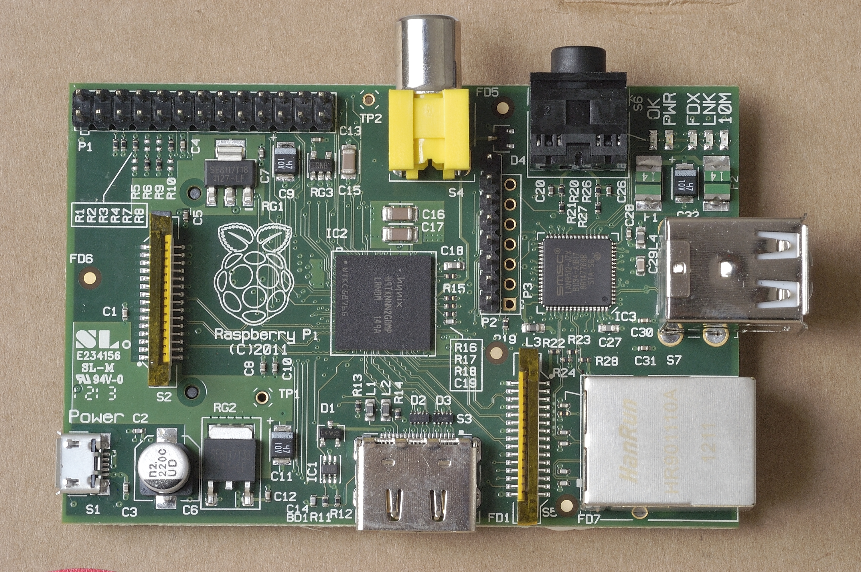
Raspberry Pi
The Raspberry Pi is an advanced microcontroller developed by the Raspberry Pi foundation to improve the scientific education of children and adults. The main reason for this was that computers are usually complex and expensive so people did not really have the option to test things out or learn coding. So the goal behind the Raspberry Pi is to offer a cheap programmable computer to experiment with. A first prototype was done in 2006 but the developers decided that the system did not have enough power. Luckily the smartphone boom followed shortly after and so better processors became available and cheaper. So the first Raspberry Pi boards could be released in 2011. Until now there have been quite some boards which mainly differ in technical specifications, size and output ports. For example there were the Model B (the first version) and a so called „Compute Module“.


The Compute Module is special because it has no built in I/O ports. These are placed on a separate I/O board:

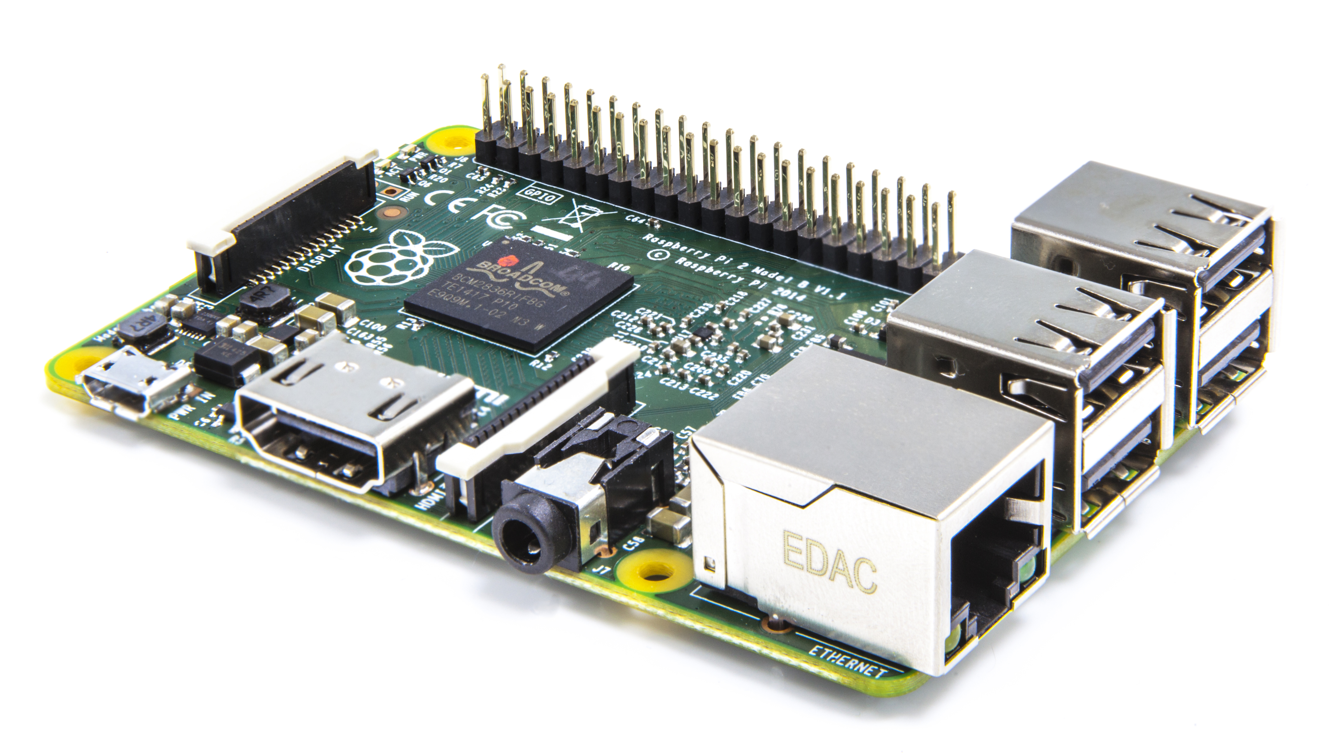
The most recent model was released in February 2015. It is called „Raspberry Pi 2 Module B“, has a quad-core processor and 1GB RAM. Due to the new chip it is around 6 times faster than the older boards if applications support multi-threading. On real multi-threading applications it can even be 7.5 times faster. It still has 40 GPIO ports so a lot of stuff can be added. It also has HDMI output, Ethernet, 4 USB ports and a micro sd-card reader (used for an sd with the operating system). The board comes at the low price of 35$ and is not much bigger than a credit card.

Technical details
- 4x900MHz Quadcore Chip
- 1GB RAM
- 4 USB 2.0 Ports
- HDMI output (full HD)
- 40 GPIO pins
- Ethernet
- 3.5mm Audio out
- Micro USB power supply
The Raspberry Pi runs with a modified Linux distribution but it also supports a special „internet of things“ version of Windows 10. Now here is a short overview on how to create an application for a Raspberry Pi:
Coding for a Raspberry Pi is quite easy because many programming languages are available. If the recommended OS „Raspbian“ is used, compilers and development environments for Python, Scratch, Java, C/C++ and Ruby are built in. So every one of these can be used to create an application for a Raspberry Pi. Scratch is mainly recommended for children because it is based on drag and drop with graphical user interfaces and Python is due to its easy grammar recommended for beginners. Beside that the chosen language mainly depends on the purpose of the application. For example Java would be good if it should be portable but it is pretty bad for complex UI because it uses a lot of resources (C/C++ would be better for that).
The main usage of a Raspberry Pi can be divided into 3 sub-categories:
Multimedia:
The Raspberry Pi is suited to work as a Multimedia centre to link TV, computer and other devices. So it is for example possible to quickly access TV shows, DVDs and emails (or other data stored on the computer). Though many modern TVs also provide these functions, using a Raspberry Pi has the advantage that the UI and desired options can be highly customized. This is an example of a Raspberry Pi Media centre:

Internet of things:
Here the Raspberry Pi is mainly used as a controller or to log data. Examples would be a Pi weather station or a controller for lights (like turning the Christmas lights on when it gets dark or per remote from a computer). This is not as exciting as the other two points but it can be extremely useful.
Science/Supercomputers:
The Raspberry Pi is also used for the sole purpose of coding. But some people brought it further, combining Raspberry Pis to a super computer, building a smartphone or a handheld out of a Raspberry Pi. Here are literally no limits to imagination. An example would be this handheld:

Here is also a cool scientific project we found on the internet:
The different LEDs show how long it takes until the space station ISS is above the current position (explanation in the video). This could be interesting for astronomers which want to watch the ISS through a telescope.
Sample project
Our Raspberry project was the PiSnake game out of the Raspberry user guide (sadly available as print version only). You can see the game at the end of our demo video and get the running sourcecode on the following link: https://www.dropbox.com/s/b92qtup3vqvwxex/snake.py?dl=0 Of course this is a very basic version of snake. There are no obstacles or a restart button when the game is over. Also the graphics could be done more beautyful. Maybe you want to improve it yourself? You only need a Raspberry Pi 2 with Raspbian (or an other OS but then it might be necessary to install a developement environment for Pyrhon).
Raspbian is freely available here: https://www.raspberrypi.org/downloads/. On this page you can also find other OS, tutorials, help and cool new projects.
Kinoma Create
The main intention of Kinoma Create, which came up in 2014, was to make the prototyping for internet of Things more easy. So it can help you to easily build prototype devices like fingerprint door opener, smart coffee machines and so on. Its special features are the capacitive colored Touchscreen as well as the included Wi-Fi and Bluetooth.
The Kinoma Create can be programmed with JavaScript and an optional XML-API. The use of the common programming language JavaScript makes it easy to create new applications for the Kinoma Create.

Technical details
- Color QVGA capacitive touchscreen
- 800 MHz Marvell ARM SoC
- Wi-Fi (802.11b/g) and Bluetooth 3.0
- 128 MB RAM, 16 MB SPI Flash
- microSD card slot
- Speaker and microphone
- Wired (USB) and portable power options — includes 2600mAh 3.7V Lithium Ion (Li-ion) 18650 rechargeable battery
- No breadboard required for many breakout-board-based sensors
- Custom, lightweight Linux distribution to support the Kinoma platform
- Digital input/output (20-36 GPIO, configurable), analog input (0-16, configurable), I²C (1 physical bus and two soft buses), UART, PWM (3)
Getting Started
All you need to start coding is the Kinoma Create Studio, which is based on eclipse. It also includes an Kinoma Create Emulator, so you can start developing even without a hardware device. Furthermore, with the Kinoma Studio it is possible to create native apps for Android and iOS. You can download it here. The Kinoma Studio is available for Mac OS and Windows in the 32bit and 64bit version. For Windows be sure to select the right Version, which depends on your installed Java Version. To check your Java version, you can use the following shell command:
java -version
For a 32 bit version you will get the following result:
//java version "1.6.0_41"//
//Java(TM) SE Runtime Environment (build 1.6.0_41-b02)//
//Java HotSpot(TM) Client VM (build 20.14-b01, mixed mode, sharing)//
If you have installed the 64 bit Version of Java you will get this result:
//java version "1.6.0_18"//
//Java(TM) SE Runtime Environment (build 1.6.0_18-b07)//
//Java HotSpot(TM) 64-Bit Server VM (build 16.0-b13, mixed mode)//
Kinoma Studio
As you can see in the image the Kinoma Studio looks and behave like the well-known Eclipse development environment.

Within the Kinoma Studio, you can download and install over 100 different sample projects. You can find them in the help section of the studio. After installing a sample project is it available in the project explorer. To deploy or debug the app, you have to open the application.xml file. You will get the following view in which you can choose between the emulator and the device. It is also possible to deploy a project on the Kinoma device over Wi-Fi.

Sample code
This is the code for a simple „Hello World“ application. When tapping the screen, the application will change the background color. As you can see, the used code is a mixture of a xml declaration (which defines the optical look) and JavaScript for the logical part. The container tag defines the view itself. It contains a simple label as well as the events (behavior tag) which are linked to a JavaScript function. The JavaScript part does the view initialization.
<program xmlns="http://www.kinoma.com/kpr/1">


	<skin id="redSkin" color="red"/>
	<skin id="blueSkin" color="blue"/>


	<style id="labelStyle" font="bold 36px" color="white" align="center,middle"/>


	<container id="MainContainer" left="0" right="0" top="0" bottom="0" skin="blueSkin" active="true">
		<behavior>
			<method id="onTouchBegan" params="container, id, x, y, ticks"><![CDATA[
				container.skin = redSkin;
			]]></method>
			<method id="onTouchEnded" params="container, id, x, y, ticks"><![CDATA[
				container.skin = blueSkin;
			]]></method>
		</behavior>
		<label left="0" right="0" top="0" bottom="0" style="labelStyle" string="$.text"/>
	</container>


    <script><![CDATA[
		application.add( new MainContainer({ text: "Hello, HCI" }));
	]]></script>

</program>
Other Sample Projects
Sources
Definition & History:
http://fritzing.org/home/
https://ti.tuwien.ac.at/ecs/teaching/courses/mclu/theory-material/Microcontroller.pdf
http://www.circuitstoday.com/microcontroller-invention-history
D. S. Yadav -Microcontrollers: Features and Applications, New Age International Pvt Ltd Publishers, 2008
http://www.vintagecalculators.com/html/the_calculator-on-a-chip.html
Arduino:
https://www.arduino.cc/en/Main/Boards
http://www.microbot.it/open2b/var/products/0/64/0-eb31ec10-700.jpg
http://www.elecfreaks.com/store/images/Arduino_Shield_JS2_01.jpg
http://cdn.shopify.com/s/files/1/0045/8932/files/stacked-shields_large.jpg?1280198233
Intel Edison:
https://software.intel.com/sites/default/files/managed/ab/52/iot_edison.png
http://download.intel.com/support/edison/sb/edisonmodule_hg_331189004.pdf[Figur 1]
https://lazure2.files.wordpress.com/2014/12/intel-make-it-wearable-winners-3-nov-20141.png
http://www.golem.de/news/intel-edison-kleinrechner-mit-arduino-artigem-board-als-breakout-1409-109137.html
http://www.intel.com/content/www/us/en/do-it-yourself/edison.html
http://www.intel.com/support/edison/sb/CS-035277.htm
http://www.elektroniknet.de/embedded/hardware/artikel/112741/
http://www.theinquirer.net/inquirer/feature/2309069/intels-mobile-focus-may-be-too-little-too-late
Raspberry Pi:
http://raspi.tv/wp-content/uploads/2012/06/DSC_31931.jpg
http://www.geeky-gadgets.com/wp-content/uploads/2014/04/Raspberry-Pi-Compute-Module2.jpg
http://cdn.liliputing.com/wp-content/uploads/2014/04/raspberry-pi-compute-module-io-board_01.jpg
https://www.raspberrypi.org/wp-content/uploads/2015/01/Pi2ModB1GB_-comp.jpeg
https://learn.adafruit.com/system/assets/assets/000/005/897/medium800/raspberry_pi_xbmc_playing_music.jpg?1396829295
http://static.neuerdings.com/1372686937/bildschirmfoto-vom-2013-07-01-154218.png
Kinoma Create:
Seiten-Werkzeuge
