Benutzer-Werkzeuge
Inhaltsverzeichnis
This wiki article is based on chapter one (7. Aktoren) of the book Prototyping Interfaces - Interaktives Skizzieren mit vvvv 1) 2), enhanced by further information from different sources.
Topic 7: Electric motors
1. Introduction
Electric motors are everywhere! Almost every mechanical movement that we see around us is caused by a electric motor. Electric motors can be divided into two basic groups, Direct Current (DC) motors, and Alternating Current (AC) motors. Although there are many designs of electric motors, the fundamental is the same. This articel give an overview of Direct current motors and their usage.
1.1 Historical review
* 1820-1822 : The Danish physicist and philosopher Hans Christian Oersted discovered the magnetic effect of electric current, a fundamental phenomenon of electromagnetism. A year later, Michael Faraday published results of its work on „electromagnetic rotation“. He designed a device in which an electrical conductor is rotated by a fixed magnet and a movable magnet in the opposite experiment by a fixed head. In 1822 Peter Barlow developed the eponymous Barlow wheel.
* 1832 : The British scientist William Sturgeon invented an additional engine precursor.
* 1827-1838 : On the European continent had Ányos Jedlik and Hermann Jacobi in the further development of the direct-current electric motor. So Jacobi developed already in 1834 the first practicable electric motor in Potsdam and endowed in 1838 in St. Petersburg, a six comprehensive boat with his self-developed 220-watt motor, thus at the same time also represented the first application of an electric motor in practice. The American blacksmith Thomas Davenport in Vermont developed a commutator motor. In its design on 25 February 1837 a patent was granted him. This provides the basis for an electric motor drive was known and developed to application compatible machine to 1837/1838.
* 1866 : Werner von Siemens patented his dynamo in 1866. It allowed for the first time a generation of electrical energy on a larger scale. This helped the electric motor to breakdown at a practicable broad application. There were at that time, some technical developments of electric motors which finally gained no meaning. This includes, among other things, the Egger-electric motor, which is constructed similar to a steam engine and the electric motorcycle by Johann Kravogl.
1.2 Basic principle
A motor is a device that converts electrical energy to mechanical energy withe the help of electro-mechanical forces. A motor uses magnets to create motion. It uses the fundamental law of all magnets: Opposites attract and likes repel. Inside an electric motor, these attracting and repelling forces create rotational motion. Electrical energy used can be from AC or DC source. It is used to create a magnet.
2. Motor types
2.1 DC motors
It’s the most primitive version of the electric motor where rotating torque is produced due to flow of electric current through the conductor inside a magnetic field. An electromagnet is the basis of an electric motor.
2.1.1 Classic DC motor
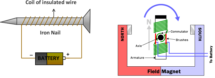
We can create a simple electromagnet by wrapping 100 loops of wire around a nail and connecting it to a battery. This nail will become a magnet having a north and south pole while the battery is connected. Such an electromagnet is created in the DC motors.
As illustrated in the diagram above, a simple motor has six parts viz.3)
- Armature or rotor : The armature is an electromagnet made by coiling thin wire around the metal rod.
- Commutator : Commutator is simply a pair of plates attached to the axle. These plates provide the two connections for the coil of the electromagnet.
- Brushes : Brushes are just two pieces of springy metal or carbon that make contact with the contacts of the commutator.
- Axle : Axle holds the armature and the commutator.
- Field magnet : Field magnet is a permanent magnet which influences electromagnet to rotate. It could be an electromagnet as well, but in most small motors it isn't in order to save power.
- DC power supply / battery : It is used to convert the armature into electromagnet.
Working of Classic DC motor
- When the electromagnet is suspend in the middle of the Field-magnet as shown in the diagram above, then according to basic law of magnetism: The north end of the electromagnet would be repelled from the north end of the Filed-magnet and attracted to the south end of the Filed-magnet. The south end of the electromagnet would be repelled in a similar way. This will result in the half-rotation of the electromagnet.
- After the half-rotation the field of electromagnet is flipped; i.e. It's south end becomes north end and vise a versa. This flipping can be achived by changing the direction of the electrons flowing in the wire. (If we flip the battery the direction of flow of electrons is also changed.)
- If the field of the electromagnet were flipped at precisely the right moment at the end of each half-turn of motion, then the rotation will be complete and the electric motor would spin freely.
- The flipping the electric field of an electric motor is accomplished by the commutator and the brushes. The commutator and brushes work together to let current flow to the electromagnet, and also to flip the direction of the flow of electrons at just the right moment.
- The contacts of the commutator are attached to the axle of the electromagnet, which makes the magnet spin.
Usage
DC motors are used in Home appliances like mixer, refrigerator, washing machine,Vacuum cleaner, dryer, fan, computers, toys etc.
2.1.2 Vibration motor
A vibrating motor is a DC motor that is improperly balanced. When we attach an off-centered weight to the motor's rotational axle, it causes the motor to vibrate. As snown in picture below, by attaching extra weight to a motor it can be converted to vibration motor! 4)
The amount of vibration can be manipulted by:
- the amount of weight that is attached
- the weight's distance from the axle
- the speed at which the motor rotates
Coin Vibration motors
Coin Vibration motors are the compact vibrating motors. They are commenly used in appliances like mobiles phones clocks etc. As the sturcture shown in the image below, a coin vibration motor is a compact DC motor with a counter weight attached to it. 5)
Usage
Vibration motor (coin vibration motor) are commanly used in Smart phones, Electric toothbrush, Electric Clocks
2.1.3 Stepper motor
A stepper motor is a special type of electric motor that moves in increments, or steps, rather than turning smoothly as a conventional motor does. The size of the increment is measured in degrees and can vary depending on the application. Typical increments are 0.9 or 1.8 degrees, with 400 or 200 increments thus representing a full circle. The speed of the motor is determined by the time delay between each incremental movement.6)
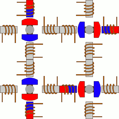
Inside the device, sets of coils produce magnetic fields that interact with the fields of permanent magnets. The coils are switched on and off in a specific sequence to cause the motor shaft to turn through the desired angle. The motor can operate in either direction (clockwise or counterclockwise). When the coils of a stepper motor receive current , the rotor shaft turns to a certain position and then stays there unless or until different coils are energized. Unlike a conventional motor, the stepper motor resists external torque applied to the shaft once the shaft has come to rest with current applied. This resistance is called holding torque.
Driving modes
There are various ways that the coils are energized, and the results on the motors shaft. Following we describe the three most important one.
1. Single-Coil Excitation
The first way is the one described previously. This is called Single-Coil Excitation, and means that only one coil is energized each time. This method is rarely used, generally when power saving is necessary. It provides less than half of the nominal torque of the motor, therefore the motor load cannot be high.
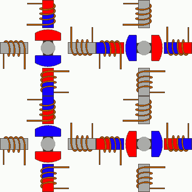
2. Full step drive
The second and most often used method, is the Full step drive. According to this method, the coils are energized in pairs. According to the connection of the coils (series or parallel) the motor will require double the voltage or double the current to operate that needs when driving with Single-Coil Excitation. Yet, it produces 100% the nominal torque of the motor.
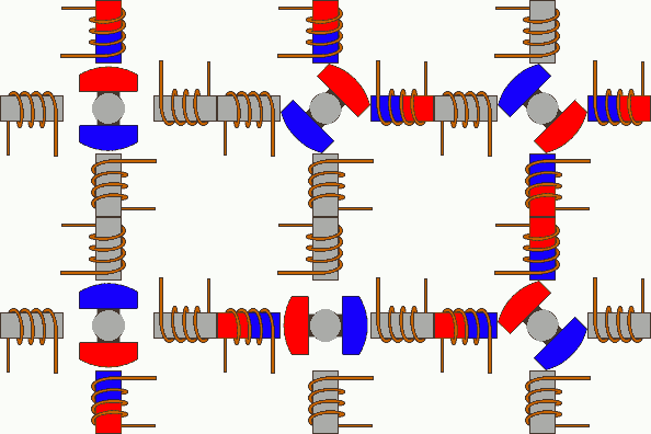
3. Half stepping
The third is a very interesting way to achieve double the accuracy of a positioning system, without changing anything from the hardware! According to this method, all coil pairs can be energized simultaneously, causing the rotor to rotate half the way as a normal step. This method can be single-coil or two-coil excitation as well.
With this method, the same motor will have double the steps per revolutions, thus double the accuracy in positioning systems. For example, this motor will have 8 steps per cycle!7)
Usage
Stepper motors have been used in computer hard drives, because they can be moved and positioned with precision. They have also been used in various robotic devices and as antenna rotators. Also in the automotive industry stepper motors are frequently used, e.g. a car have 40-50 stepper motors plugged.
2.1.4 Servo motor
To fully understand how the servo works, you need to take a look under the hood. Inside there is a pretty simple set-up: a small DC motor, potentiometer, and a control circuit. The motor is attached by gears to the control wheel. As the motor rotates, the potentiometer's resistance changes, so the control circuit can precisely regulate how much movement there is and in which direction.
When the shaft of the motor is at the desired position, power supplied to the motor is stopped. If not, the motor is turned in the appropriate direction. The desired position is sent via electrical pulses through the signal wire. The motor's speed is proportional to the difference between its actual position and desired position. So if the motor is near the desired position, it will turn slowly, otherwise it will turn fast. This is called proportional control. This means the motor will only run as hard as necessary to accomplish the task at hand.
Controlling servo motor
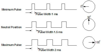
Servos are controlled by sending an electrical pulse of variable width, or pulse width modulation (PWM), through the control wire. There is a minimum pulse, a maximum pulse, and a repetition rate. A servo motor can usually only turn 90 degrees in either direction for a total of 180 degree movement. The motor's neutral position is defined as the position where the servo has the same amount of potential rotation in the both the clockwise or counter-clockwise direction. The PWM sent to the motor determines position of the shaft, and based on the duration of the pulse sent via the control wire; the rotor will turn to the desired position. The servo motor expects to see a pulse every 20 milliseconds (ms) and the length of the pulse will determine how far the motor turns. For example, a 1.5ms pulse will make the motor turn to the 90-degree position. Shorter than 1.5ms moves it to 0 degrees, and any longer than 1.5ms will turn the servo to 180 degrees, as diagramed below
When these servos are commanded to move, they will move to the position and hold that position. If an external force pushes against the servo while the servo is holding a position, the servo will resist from moving out of that position. The maximum amount of force the servo can exert is called the torque rating of the servo. Servos will not hold their position forever though; the position pulse must be repeated to instruct the servo to stay in position.
3. Connect motors to arduino
3.1. Connect DC motor
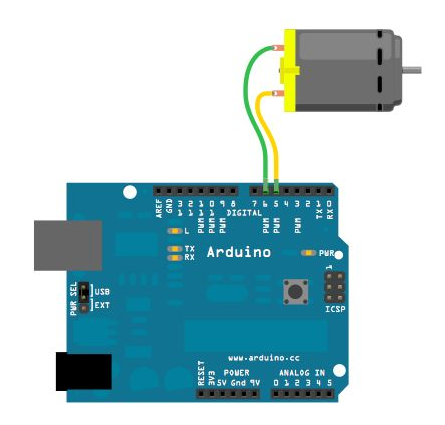
It is very easy to connect a DC motor to your arduino board. All you need is a small dc motor, wires for your motor and an arduino board. Connect your board via usb to your PC and start the Arduino IDE.
Here the circuit:
Now you just have to upload coding below onto your arduino board:
//2-Way motor control

int motorPin1 =  5;    // One motor wire connected to digital pin 5
int motorPin2 =  6;    // One motor wire connected to digital pin 6

// The setup() method runs once, when the sketch starts

void setup()   {
  // initialize the digital pins as an output:
  pinMode(motorPin1, OUTPUT);
  pinMode(motorPin2, OUTPUT);
}

// the loop() method runs over and over again,
// as long as the Arduino has power
void loop()
{
  rotateLeft(150, 500);
  rotateRight(50, 1000);
  rotateRight(150, 1000);
  rotateRight(200, 1000);
  rotateLeft(255, 500);
  rotateRight(10, 1500);
}

void rotateLeft(int speedOfRotate, int length){
  analogWrite(motorPin1, speedOfRotate); //rotates motor
  digitalWrite(motorPin2, LOW);    // set the Pin motorPin2 LOW
  delay(length); //waits
  digitalWrite(motorPin1, LOW);    // set the Pin motorPin1 LOW
}

void rotateRight(int speedOfRotate, int length){
  analogWrite(motorPin2, speedOfRotate); //rotates motor
  digitalWrite(motorPin1, LOW);    // set the Pin motorPin1 LOW
  delay(length); //waits
  digitalWrite(motorPin2, LOW);    // set the Pin motorPin2 LOW
}

void rotateLeftFull(int length){
  digitalWrite(motorPin1, HIGH); //rotates motor
  digitalWrite(motorPin2, LOW);    // set the Pin motorPin2 LOW
  delay(length); //waits
  digitalWrite(motorPin1, LOW);    // set the Pin motorPin1 LOW
}

void rotateRightFull(int length){
  digitalWrite(motorPin2, HIGH); //rotates motor
  digitalWrite(motorPin1, LOW);    // set the Pin motorPin1 LOW
  delay(length); //waits
  digitalWrite(motorPin2, LOW);    // set the Pin motorPin2 LOW
}
3.2. Connect Servo motor
To get started controlling a servo with your Arduino, you only need to connect three pins. There are two pins for power and ground. For a small servo or just for testing, you can connect these directly to the Arduino. If you are controlling a large servo motor, you might want to use an external power source. Just remember to connect the ground from the external source to the ground of the Arduino. Arduino Servo The third pin is the pulse, or signal pin. This accepts the signal from your controller that tells it what angle to turn to. The control signal is fairly simple compared to that of a stepper motor. It is just a pulse of varying lengths. The length of the pulse corresponds to the angle the motor turns to. Typically a pulse of 1.25 milliseconds causes the motor to rotate to 0 degrees and a pulse of 1.75 milliseconds turns it 180 degrees. Any length of pulse in between will rotate the servo shaft to its corresponding angle. Some servos will turn more or less than 180 degrees, so you may need to experiment.
Below you see the circuit:
Following code is also in examples of Arduino IDE; just upload to arduino board and have fun:
#include <Servo.h>

Servo myservo;  // create servo object to control a servo
                // a maximum of eight servo objects can be created

int pos = 0;    // variable to store the servo position

void setup()
{
  myservo.attach(9);  // attaches the servo on pin 9 to the servo object
}


void loop()
{
  for(pos = 0; pos < 180; pos += 1)  // goes from 0 degrees to 180 degrees
  {                                  // in steps of 1 degree
    myservo.write(pos);              // tell servo to go to position in variable 'pos'
    delay(15);                       // waits 15ms for the servo to reach the position
  }
  for(pos = 180; pos>=1; pos-=1)     // goes from 180 degrees to 0 degrees
  {
    myservo.write(pos);              // tell servo to go to position in variable 'pos'
    delay(15);                       // waits 15ms for the servo to reach the position
  }
}
3.3. Connect Vibration motor
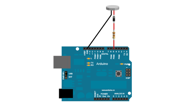
To make a vibration motor vibrate is very simple. All we have to do is add the needed voltage to the 2 terminals. A vibration motor has 2 terminals, usually a red wire and a blue wire. The polarity does not matter for motors. Just connect vibration motor like shown below in the circuit. The diode acts as a surge protector against voltage spikes that the motor may produce.
After you upload this coding, vibration motor will vibrate every minute for one second.
const int motorPin = 5;

void setup()
{
pinMode(motorPin, OUTPUT);
}

void loop()
{
digitalWrite(motorPin, HIGH);
delay(1000);
digitalWrite(motorPin, LOW);
delay(59000);
}
So, you see, it is really simple to have first contact with controller driven motors. Further we will describe small projects, trying to clearify open questions.
4. Sample applications
4.1 VVVV Arduino starwars theme
Very simple, using an arduino and play melody basic program, create a music playing speaker out of a vibration motor. Instead of pulsing signal to a speaker, signal is pulsed to a motor varying how fast it can spin and when it spins. 8)
As the motor vibrates it transfer the kinetic energy into the air. Depending on intensity of vibrating we hear different music notes. So manipulating frequencies can let us compose some masterpieces :)
So connect your vibration motor like in the picture below (you can ignore the knob):
Now, to test your Circuit, upload following code onto your arduino:
#define  c3    7634
#define  d3    6803
#define  e3    6061
#define  f3    5714
#define  g3    5102
#define  a3    4545
#define  b3    4049
#define  c4    3816    // 261 Hz
#define  d4    3401    // 294 Hz
#define  e4    3030    // 329 Hz
#define  f4    2865    // 349 Hz
#define  g4    2551    // 392 Hz
#define  a4    2272    // 440 Hz
#define  a4s   2146
#define  b4    2028    // 493 Hz
#define  c5    1912    // 523 Hz
#define  d5    1706
#define  d5s   1608
#define  e5    1517
#define  f5    1433
#define  g5    1276
#define  a5    1136
#define  a5s   1073
#define  b5    1012
#define  c6    955

// Define a special note, 'R', to represent a rest
#define  R     0

// SETUP ============================================
// Set up speaker on a PWM pin (digital 9, 10 or 11)
int speakerOut = 9;
// Do we want debugging on serial out? 1 for yes, 0 for no
int DEBUG = 1;

void setup() {
  pinMode(speakerOut, OUTPUT);
  if (DEBUG) {
    Serial.begin(9600); // Set serial out if we want debugging
  }
}


// star wars theme
int melody[] = {  f4,  f4, f4,  a4s,   f5,  d5s,  d5,  c5, a5s, f5, d5s,  d5,  c5, a5s, f5, d5s, d5, d5s,   c5};//
int beats[]  = {  21,  21, 21,  128,  128,   21,  21,  21, 128, 64,  21,  21,  21, 128, 64,  21, 21,  21, 128 };

int MAX_COUNT = sizeof(melody) / 2; // Melody length, for looping.

// Set overall tempo
long tempo = 10000;
// Set length of pause between notes
int pause = 1000;
// Loop variable to increase Rest length
int rest_count = 50; //<-BLETCHEROUS HACK; See NOTES

// Initialize core variables
int toneM = 0;
int beat = 0;
long duration  = 0;

// PLAY TONE  ==============================================
// Pulse the speaker to play a tone for a particular duration
void playTone() {
  long elapsed_time = 0;
  if (toneM > 0) { // if this isn't a Rest beat, while the tone has
    //  played less long than 'duration', pulse speaker HIGH and LOW
    while (elapsed_time < duration) {

      digitalWrite(speakerOut,HIGH);
      delayMicroseconds(toneM / 2);

      // DOWN
      digitalWrite(speakerOut, LOW);
      delayMicroseconds(toneM / 2);

      // Keep track of how long we pulsed
      elapsed_time += (toneM);
    }
  }
  else { // Rest beat; loop times delay
    for (int j = 0; j < rest_count; j++) { // See NOTE on rest_count
      delayMicroseconds(duration);
    }
  }
}

// LET THE WILD RUMPUS BEGIN =============================
void loop() {
  // Set up a counter to pull from melody[] and beats[]
  for (int i=0; i<MAX_COUNT; i++) {
    toneM = melody[i];
    beat = beats[i];

    duration = beat * tempo; // Set up timing

    playTone();
    // A pause between notes...
    delayMicroseconds(pause);

    if (DEBUG) { // If debugging, report loop, tone, beat, and duration
      Serial.print(i);
      Serial.print(":");
      Serial.print(beat);
      Serial.print(" ");
      Serial.print(toneM);
      Serial.print(" ");
      Serial.println(duration);
    }  }
}
Well, maybe you can't hear any star wars theme, for that connect a servo motor instead of vibration motor.
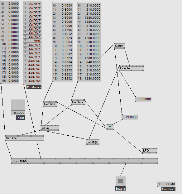
So, you see, it works! But now we want to compose live via vvvv 9). At picture below you see the vvvv patch. In spread in the middle you see 19 values, these are our music notes, based on intensity of vibration. Next to this spread there are values for durations of each music note. For example: the 8th musicnote with intensity 0.9323 will be played for 1280ms.
Now you can adjust the values and compose your personal masterpiece or another nice tune, by extend the spread or changing the intensity and duration values.
5. Presentation
- VVVV patch - VVVV Patch

