Benutzer-Werkzeuge
Inhaltsverzeichnis
Marker Tracking
1. Introduction
Fiducial Marker Tracking and ARTK Tracking give the possibility to build prototypes really fast with no need for special or expensive hardware.
You simply need a webcam which is integrated today in almost every notebook, or can be bought low-priced and the markers. The markers for tracking and the augmented reality prototypes can be simply printed and put on almost every thinkable object you want to use for the prototype you build.
![]()
2. Markers and Hardware
2.1. Fiducial Markers
![]()
From each marker these attributes are extracted from the camera picture:
- Individual ID
- X-position
- Y-position
- Rotation
From the picture of Fiducial Markers there can be no Z-Position extracted, so they can only be tracked in a 2D-Space.
But the Tracking is pretty robust and faster, compared to the AR-Markers.
There are two kinds of markers: White markers on black background and black markers on white background.
You should always test and find out which kind of colouring works better in the specific case.
In the assets folder of the Fiducial Tracking Patch from the Website of the book you can find a PDF-File with 215 different Fiducial Markers.
![]()
![]()
Fiducial-Markers on different objects
2.2. Augmented Reality Markers
![]()
From each marker these attributes are extracted from the camera picture:
- Individual ID
- X-position
- Y-position
- Z-position
- Rotation
For 3D animation visualization need AR Marker, but in Fiducial Markers can't do 3D tracking. The Augmented Reality Markers used in the „prototyping Interfaces“ Book look a little bit like QR-Codes.
2.3. Camera
For the tracking of the Fiducial-Markers and the Augmented-Reality Markers any common Webcam is sufficient.
![]()
The Camera field of view and the Beamer-Projection should always be congruent, so that no extra justification in the program is needed and the animations and triggers for the markers are in the right position.
![]()
3. Fiducial Tracking
With fiducial tracking you can get the position of a special marker, which can be attached to any object, by a camera picture.
3.1 History
The fiducial markers have been developed by a group at the Universitat Pompeu Fabra in Barcelona.
This reacTIVision framework was designed as part of the Reactable, a interactive music table with a Tangible User Interface.
![]()
3.2 How it works
The camera stream is converted to a black and white image with a defined threshold. This image is then segmented into black and white regions, in which the algorithm searches for known patterns. If a pattern is found, this pattern is compared to an internal dicitonary from which the unique marker id is extracted.
3.3. VVVV-Code
![]()
The FiducialTracking Node needs a video or a camera picture as input.
Depending on the light situation you might need to adjust the threshold value for the marker detection. To test the value you can ativate the Show Thresholded Toggle Button.
This node gives us with the correct input values the ID, X- and Y-Position and Orientation(Roatation) of every Fiducial Marker that is detected from the input-stream and the Video-Signal which can be used as background to show something on it.
You might need to map the X and Y-Position Values from a diffrent coordinate system to the VVVV-Coordinate System from -1 to 1. This can be done with two map nodes.
In this example, the Position of the marker is used to show a segment at the corresponding position which is manipulated by the rotation of the marker. This generated segment is the grouped with the original video-stream and then rendered.
![]()
The resulting output with the combination of the original video and the generated segment.
3.4. Examples
3.4.1 Noteput
![]()
Noteput is a table with staves on which you can lay diffrent musical notes.
You can combine many notes, which are available in diffrent forms. If you put on note on the table, the corresponding note is played. Through this principle, three diffrent senses should be combined to get a better learning experience. There is a free and a challenge mode available. The sounds that are played can be changed between different instruments.
![]()
Under each physical note there is a different Fiducial-Marker attached. These markers can't be seen from above but are recognized by a camera under the table.
![]()
The camera is located directly under the table and the projection of the lines and the other optical parts that are shown on the table are achieved by placing a mirror under the table and pointing the beamer on the mirror, so the projection is reflected on the table surface.
![]()
3.4.2 Computer Vision Hair Trimmer
![]()
This guy wants to cut his own hair. The front side is no problem, because he can see enough and he only cuts it to a specific length.
But the backside of his head isn't that easy to trim, because he wants to shave the hearline without cutting massive edges into the hair, so he modified his trimmer with an arduino and used fiducial markers attached to a helmet to calculate the correct hairline.
![]()
For his attempt he always calculates an imaginary line between the two markers he has attached, at the height of the wanted hairline, to the helmet he wears. If the trimmer which is also tracked with a marker is below this line the arduino applies power to it and if it is above the wanted hairline the arduino powers the trimmer off.
4. Augmented Reality
Augmented Reality (AR) is a combination of real world and digital data. AR allows to project virtual objects at our surroundings. Encyclopedia Britannica said AR: “Augmented reality, in computer programming, a process of combining or ‘augmenting’ video or photographic displays by overlaying the images with useful computer-generated data.” VVVV has ARTK+Tracker Node, special markers read positions of the objects in space with a camera. By this object can be projected with the markers.
Applications in our Surroundings
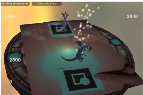
Game Yu Gi Oh allows multiple AR Marker tracking to play game. The displaying objects on markers can be changed depends on user what kind of objects they like to use as well as game and action sounds. One object can attack another when two objects will be nearer and which object will be loser, it will be depends also on user how they want from programmer.
Unlike virtual reality, digital layer drawn on a „real“ picture or video input.
4.1 Augmented Reality and VVVV
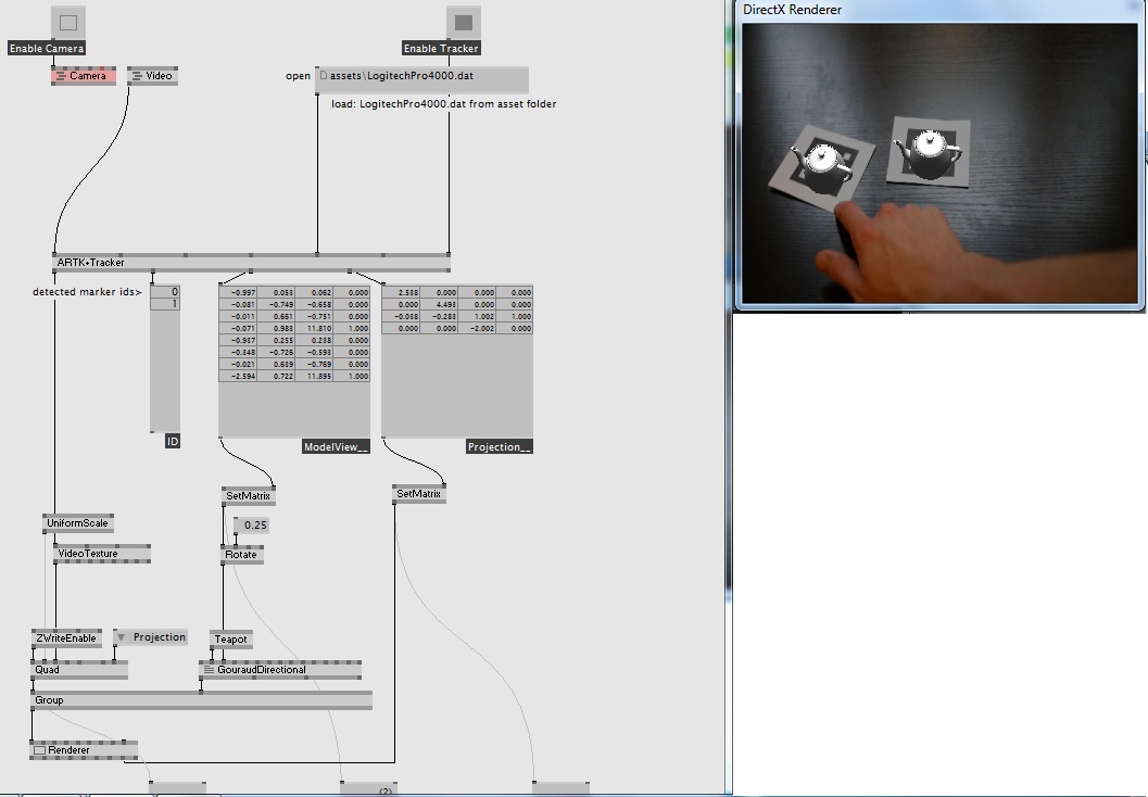
VVVV is able to use Augmented Reality with the help of the node ARTK+Tracker. An example patch called AugmentedReality helps us understand how the node works. The patch can be downloaded here. To use the patch properly, the addonpack must be downloaded beforehand from the VVVV website.

The patch uses nodes which are able to track markers via a video input such as a video or webcam stream.
| Node Name | Explanation |
|---|---|
| Renderer | the screen. A group of nodes is connected to the Renderer by the Group node. |
| Group | this node groups everything that needs to be shown on the Renderer, in this case – the Quad and GouraudDirectional |
| Quad | A quad is basically a rectangle. In this case, we use the Quad to display the camera picture. If you remove the node connection, you can see that the patch is still working, but that the background now becomes black. Above the Quad node, you can see ZWriteEnable, and VideoTexture. |
| ZWriteEnable | This node allows us to project a 2d node into a 3d. In this case, since Quad is actually a 2d node, and we want to project it on a Z of a 3d plane, we have to give it a Z property. Basically, Quad has no Z property, only X and Y. By using this node, we allow it to have a Z value. |
| VideoTexture | Quad has an input Texture. At this point, you can also connect FileTexture. Try connecting FileTexture, and then rightClick the top left dot. Now select a picture. What you should see is that the background is now a picture, and not the camera video, or default video.VideoTexture allows us to fill an object with a video. To try this with other objects, you can also apply a video texture to GouraudDirectional. |
| GouraudDirectional | This is the node which controls what will be drawn above the marker if detected. Here you can change what will be projected. Try connecting a Sphere node. Now you can see a Sphere is there instead of a teapot. The GouraudDirectional also allows us to simulate a studio light. Imagine a light which shines onto an object from far away – this will cause shadows and shading on the object. The GouraudDirectional needs a matrix to know where to draw the Object (here – Teapot). This is why it is connected to Rotate. If you see the rotate – it is connected to SetMatrix. |
| SetMatrix | This node takes the values from the ARTK+Tracker and then sorts them into a matrix so that the Renderer can easily use these values. The SetMatrix which is connected to GouraudDirectional shows where the marker is detected on the video input. The second SetMatrix defines where in relation to the marker the Teapot should be drawn. |
4.2 Simulating Sun and Earth
The patch can be further enhanced. Here is the zip file again, but this time the patch referred is called _root.
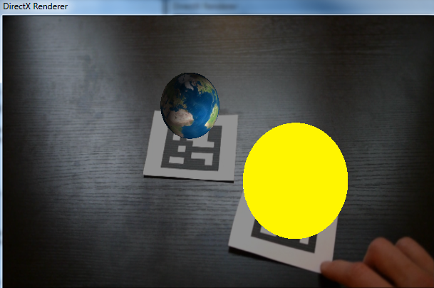
By applying textures and using nodes to Sphere instead of the Teapot a planet orbiting the sun can be visualized. There is a problem however. Since the ARTK+Tracker scans the picture from the bottom, if 2 textures are sent to the Spheres, the marker which is first detected takes the first texture, and the one detected second will take the second.
In other words, the textures are not constant. The textures may jump from one Sphere to the other. To ensure the Texture „sticks“ to one Sphere.
There are several key nodes in the _root patch.
| Node | Function |
|---|---|
| AugmentedReality | The patch is explained here |
| Sort | The ids of the Markers detected by the webcam or on the video are sorted here. This is the first step to ensure the output are not mixed. This is then passed onto a = node. If the output is already what we want (here 0 and 1) then it is passed on. Else the 0 and 1 are passed on. |
| 3DWorld | This is the most important node in the patch. This node implements the GouraudDirectional from here. The main difference between 3DWorld and GouraudDirectional is the comparing part of the vector. What this does is compare the vectors of the marker locations. This assigns a fixed texture to the object (here - Sphere to visualize plant). The textures will not jump due to the vector comparing. |
View of the final project.
5. Presentation
A presentation explaining of the topics above can be downloaded at the following link. pdf file of presentaton.


